Certain radios stand out because of their cabinet styling or unusual circuirty. The Pilot radio described in this article scores on both accounts. (editor)
The 11-tube Pilot radio, shown in Figure 1, was made by the Pilot Radio and Tube Company of Lawrence, Massachusetts. Although it is identified as the Model 40174, it is commonly known as the "All-Wave," and it sold for 99.50 in the 1932 radio season.
The radio has some unusual feature. The shape of the cabinet is different and looks like a "stretched cathedral." Even the speaker cutout is much wider than it is high. The layout of the controls and dials on the front panel is symmetrical, but why are there two sets of control knobs and two dials?
The name "All-Wave" provides a clue. The cabinet contains two chassis. One is the standard, 7-tube, AC-operated, broadcast-band shortwave converter. This combination covers 545 to 11 meters.A rear view of the radio is shown in Figure 2.
The Converter
The shortwave (SW) converter is probably the same as the one shown on the Pilot page 1-6 of Rider's Volume 1. Its tube complement consists of one each of the following types: 224 RF amplifier, 224 mixer, 227 oscillator and 280 rectifier. The converter features a bandswitch, thus eliminating the nuisance of changing plug-in coils. A sixth position of the bandswitch cuts the converter out of the circuit and connects the antenna to the broadcast receiver chassis. The converter's output frequency is 550 Kc. It is necessary to tune the broadcast radio to that frequency when the converter is being used.
THE BROADCAST RECEIVER
The broadcast band reciever appears to be a straightforward superhet with the following tube complement: (1) Type 224, (2) Type 235, (2) Type 227, Type (1) 247, and (1) Type 280. Like the converter, the broadcast-band radio has its own power supply.
In the same model year, Pilot also offered a 7-tube superhet in either a console cabinet or a modernistic tabletop.
Introductory advertising for the "All-Wave" model, circa 1931, called the "Pilot All-Wave Super Heterodyne 11-Tube Super Wasp." Inclusion of the Super-Wasp name was probably an attempt to connect the new radio with the highly successful Pilot Super Wasp reciever of 1928.
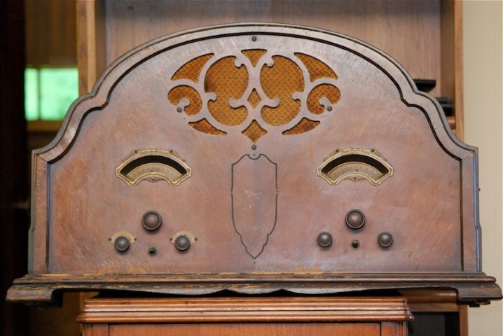
Figure 1. Front view of the Pilot Model 40174 " All wave" receiver. - click to enlarge photo
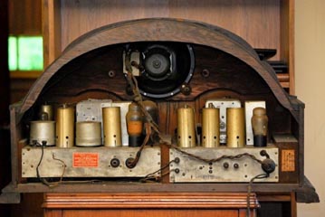
Figure 2. Back view of the Pilot Model 40174 receiver showing both chassis.- click to enlarge photo
Pilot's use of a standard broadcast reciever and an SW converter in a single unit was ingenious. A home-type reciever capable of tuning as high as 11 meters was not common in 1931. The use of bandswitching to cover such a wide tuning range was also uncommon. During that time period, the manufacturers of Ham radio recievers, such as National and Hammarlund, were still using plug in coils.
(Frank Moore, 4623 Phillips Ave., Billings Montana 59101)
Frank Moore has been collecting radios for about 30 years. Although he prefers "3-dialers," his electric stash includes Atwater Kent breadboards and Scott radios.